Introduction
Pressure vessels have multiple nozzle openings for various requirements, some nozzles are small and are used as instrumentation nozzles, some nozzles are used for process and few are man hoes. Usually, Nozzles that are tangential or on critical locations like the knuckle need to be qualified using FEA. Analyzer has done 1500+ nozzle analyses for clients in India and abroad. The nozzles are subjected to internal pressure and design nozzle loads. It is very critical to have a proper mesh so that membrane and membrane + bending stresses can be evaluated and compared with the allowable stress values as provided in different codes.
Workflow
Collecting all the information from the GA drawing
- Preparing a Finite Element Analysis Model for Nozzle to shell junction by capturing important and critical features.
- Preparing a report that complies with all the requirements as per the codal requirements.
Challenges
- Preparing CAD/ FEA Model to capture complete Stress Distribution near the junction by capturing the fillets and welds.
- Nozzle Load Application in FEA at nozzle to shell junction and transferring to flange face.
SOLUTION
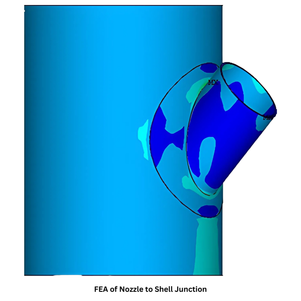
The Nozzle to Shell junction was analysed using the finite element method to determine the structural strength against the various applicable loading like internal pressure, nozzle loads & combination. To assess strength for the structure, guidelines from ASME BPVC (Boilers & Pressure Vessels Code) Section VIII Div. 2, Part 5 were utilized. For evaluating various stresses across nozzle & shell thickness.
Stress linearization is carried out across nozzle & shell thicknesses. The results showed that the induced stresses were well within the acceptable limits as per guidelines. Hence, the design is safe.
BENEFITS
- Better insights on design modifications of a particular nozzle for alternate applications
- Localized failure can be removed at design stage itself avoiding dangers of vessel in- service failure
- Optimized design with reduced material cost