
Finite Element Analysis (FEA) in Vibration Analysis: An In-Depth Guide
April 23, 2025
Defence Engineering Services: The Role of Simulation Analysis
June 28, 2025
Introduction
The oil and gas industry operates under extreme conditions, from deep-sea drilling to high-pressure refining processes. With vast investments at stake, companies must ensure that their infrastructure is not only efficient but also resilient against mechanical stress, environmental challenges, and unforeseen failures. Advanced engineering techniques enable professionals to model, test, and refine designs before implementation, reducing risks and optimizing performance.
The Role of Engineering Simulations and Digital Modelling
In an industry where precision dictates success, computational simulations and digital modelling have become indispensable. Predictive analysis allows engineers to forecast potential weak points, ensuring that drilling rigs, pipelines, and processing units can endure demanding operational loads. These technologies support real-time problem-solving, minimizing downtime and improving long-term sustainability.
Why Is Simulation & Design So Important?
- Safety & Reliability: Offshore platforms, pipelines, and refining equipment must function under intense environmental forces. Predictive modelling ensures that critical components meet regulatory standards and perform reliably over time.
- Efficiency Optimization: Engineers use advanced simulations to analyse fluid behaviour, thermal performance, and material interactions, leading to improved energy efficiency and reduced operational costs.
- Innovative Design: Digital models facilitate better material selection, optimized geometries, and streamlined production processes, enabling companies to refine designs before committing to full-scale fabrication.
A Step Toward Smarter Energy Solutions
By leveraging high-precision engineering tools, oil and gas companies are driving innovation toward more resilient and cost-effective solutions. Whether it’s optimizing drilling techniques, enhancing transportation networks, or refining production methodologies, modern technology continues to shape the industry’s future. As the sector moves towards more sustainable practices, advanced simulation and modelling will remain at the heart of its evolution.
Smart Design: Building the Backbone of Oil & Gas Infrastructure
In the oil and gas industry, effective design is the foundation for operational excellence, safety, and long-term performance. From offshore platforms and subsea pipelines to pressure vessels and refineries, each structure must be engineered to meet demanding environmental, mechanical, and regulatory requirements.
A robust design process not only optimizes efficiency and cost but also ensures compliance with global codes and standards that govern the industry.
Why Design Matters in Oil & Gas
Oil and gas infrastructure must perform reliably under extreme pressures, temperatures, corrosive fluids, and dynamic loading conditions like waves, wind, and seismic activity. A failure at the design stage can lead to catastrophic operational issues, environmental disasters, and financial loss.
Design in this sector must meet international engineering codes, anticipate real-world conditions, and be prepared for multi-decade operational lifespans.
Key Design Components
Pressure Vessels & Storage
Design Codes:
- ASME Boiler and Pressure Vessel Code Section VIII Div. 1 & 2 – For pressure containment design.
- API 650 / API 620 – For atmospheric and low-pressure storage tanks.
- Critical for withstanding internal pressure, corrosion, and thermal gradients.
Pipeline Systems
Design Codes:
- ASME B31.3 – For process piping in refineries and plants.
- ASME B31.4 / B31.8 – For liquid and gas transmission pipelines.
- DNV-ST-F101 – For subsea pipeline systems.
- Must be optimized for pressure, flow rate, thermal expansion, and corrosion resistance.
Offshore Platforms & Subsea Structures
Design Codes:
- API RP 2A-WSD / API RP 2SIM – For fixed offshore structures.
- ISO 19901 & ISO 19902 – For structural integrity and offshore design.
- NORSOK N-001 / DNVGL-ST-N001 – For Norwegian offshore and subsea standards.
- Designed for dynamic loads including waves, wind, current, and seismic activity.
Heat Exchangers, Separators, and Skids
Design Codes:
TEMA (Tubular Exchanger Manufacturers Association) Standards – For shell and tube heat exchangers.
ASME Section VIII – For pressure-rated process equipment.
- Design considers thermal efficiency, compactness, and material compatibility.
Structural Steel for Racks and Equipment Support
Design Codes:
- AISC 360 – American steel construction code.
- Eurocode EN 1993 – For structural steel in European projects.
- IS 800 – For Indian standards in steel structure design.
- Structural components must be designed for static and dynamic loads including equipment vibrations.
Essential Design Considerations
- Material Selection:
Based on corrosion environment, H₂S content (per NACE MR0175 / ISO 15156), temperature range, pressure rating, and mechanical loadings. - Load Combinations:
Designers must account for a mix of dead loads, live loads, thermal expansion, hydrodynamic and seismic forces (as per API RP 2EQ, ASCE 7, Eurocode 8, etc.). - Hazard Mitigation & Safety:
Designs incorporate provisions for explosion protection, gas detection, fireproofing, and emergency shutdown—aligned with API 521, NFPA 30, and IEC 61508 standards. - Compliance and Regulatory Requirements:
All design outputs are subject to third-party verification or client audit in accordance with industry-specific codes (e.g., DNVGL, Lloyd’s Register, ABS, or BV).
Design Tools Used
To ensure compliance and accuracy, engineers use sophisticated design and modelling tools:
- AVEVA E3D / PDMS – For 3D plant layout and clash detection.
- AutoCAD Plant 3D – For piping and instrumentation diagrams (P&IDs).
- SolidWorks / Inventor / CATIA – For equipment modelling and structural design.
- Smart Plant – For integrated engineering and document management.
- ROHR2 / CAESAR II – For piping flexibility and stress design.
Below are some examples of CAD projects
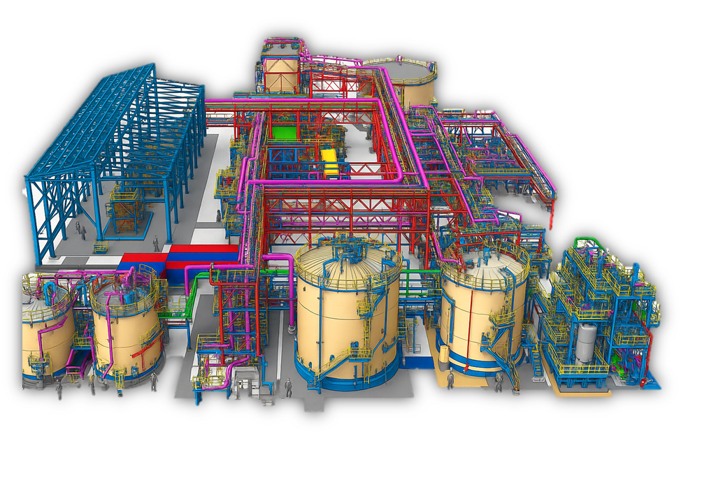
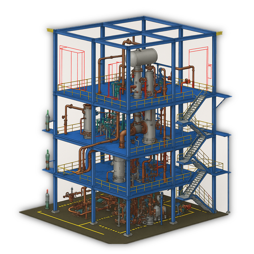
Fig : 3D model of different structures in oil and gas industry
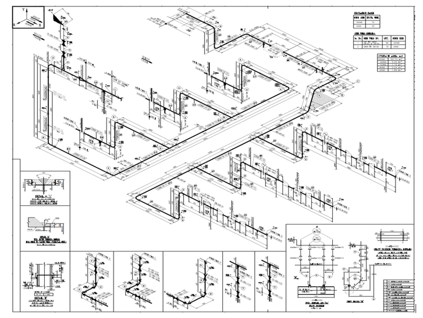
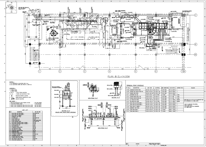
Fig : Example image of piping layout
FEA in oil & gas: Ensuring Structural Strength and Safety Under Pressure
Once the design is conceptualized, Finite Element Analysis (FEA) plays a vital role in validating its structural integrity. In the oil and gas industry—whether offshore or onshore—equipment is exposed to high pressures, dynamic loads, corrosion, and fatigue. FEA enables engineers to simulate these conditions, ensuring safety, reliability, and compliance with international codes before fabrication or installation begins.
FEA minimizes physical prototyping, improves safety, and verifies compliance with global standards by analysing stress, strain, deformation, buckling, and fatigue
Why FEA is Critical in Oil & Gas
Oil and gas infrastructure is designed to operate in volatile, high-stakes environments. In both onshore processing facilities and offshore installations, unexpected failures can lead to environmental disasters, shutdowns, or loss of life. FEA provides engineers with critical insight into structural behaviour under real-world and extreme conditions—mitigating risk at the earliest stages.
Key Applications of FEA
Offshore Applications
Subsea Pressure Vessels & Connectors
- Codes & Standards: ASME Section VIII Div. 2, DNVGL-ST-F101, API 17D
- FEA validates collapse resistance, gasket sealing integrity, and fatigue life in high-pressure, high-temperature (HPHT) environments.
Jackets, Risers & Topside Modules
- Codes & Standards: API RP 2A-LRFD, ISO 19902, DNVGL-ST-N001
- Analysis includes global deformation under wave loading, hydrodynamic fatigue, and lift/transportation conditions.
Mooring and Anchoring Systems
- Codes & Standards: API RP 2SK, DNVGL-OS-E301
- FEA assesses cyclic tension, soil-structure interaction, and connector stress.
Onshore Applications
Pressure Vessels, Separators & Heat Exchangers
- Codes & Standards: ASME Section VIII Div. 2, TEMA, EN 13445
- Used in refineries, terminals, and LNG plants. FEA checks for pressure-induced stresses, local loads, and nozzle reinforcements.
Piping Networks & Pipe Supports
- Codes & Standards: ASME B31.3, B31.4, API 579-1/ASME FFS-1
- FEA validates integrity under thermal expansion, wind, seismic events, and transient pressure surges.
Storage Tanks & Spheres
- Codes & Standards: API 650, API 620, AWWA D100
- Shell stability, roof load distribution, wind buckling, and anchorage are modelled via shell and contact elements.
Steel Structures for Process Equipment
- Codes & Standards: AISC 360, IS 800, Eurocode EN 1993
- Skid frames, platforms, pipe racks, and equipment supports are evaluated for combined gravity, thermal, and seismic loads.
Foundation & Soil-Structure Interaction (SSI)
- Codes & Standards: IS 456, ACI 318, Eurocode 7, API RP 2GEO
- Nonlinear FEA evaluates foundation settlement, uplift resistance, and dynamic base isolation under earthquake conditions.
Types of FEA Performed
- Static Structural Analysis – Evaluate operating and peak load conditions.
- Thermal-Structural Coupling – Crucial for equipment exposed to high temperature gradients (e.g., heaters, reactors).
- Modal Analysis – Avoid resonance with machinery-induced vibrations.
- Buckling Analysis – For vertical vessels, tank shells, and slender structures.
- Fatigue Life Estimation – Especially for load-cycled components like risers or pump skids.
- Creep Analysis – For equipment operating at elevated temperatures over long durations.
- Seismic & Blast Analysis – For facilities in high seismic zones or with explosion risk (per API 752, ASCE 7, Eurocode 8).
FEA Tools Used in Industry
- ANSYS Mechanical / Workbench – Multi-physics simulations for complex assemblies.
- ABAQUS / SIMULIA – Nonlinear, contact, and fracture mechanics analysis.
- STAAD.Pro – Widely used for structural steel and RCC frame analysis.
- PV Elite – Specialized for pressure vessel design validation.
- SACS – Preferred for offshore jackets and platform analysis.
- ROHR2 / CAESAR II – For piping flexibility and code compliance.
- Autodesk Nastran / Inventor FEA – For plant skids, supports, and lightweight assemblies.
Documentation & Compliance
All FEA work is documented meticulously for third-party review and client validation:
- Code mapping (ASME, API, ISO, DNV)
- Mesh sensitivity analysis and validation
- Results interpretation and acceptance criteria
- Load combinations and boundary conditions
- Safety factors and material certifications
Certifications may be required by DNV, ABS, BV, Lloyd’s Register, or local authorities.
From deep sea installations to desert processing units, FEA is indispensable in modern oil and gas engineering. It offers the insight needed to design confidently, reduce failure risks, and deliver high-performance systems that thrive in some of the harshest conditions on Earth.
Here are a few examples of projects successfully delivered by Analyzer in the oil and gas sector, highlighting our deep domain expertise, precision in engineering simulations, and ability to solve complex flow and structural challenges. These projects reflect our commitment to safety, operational efficiency, and innovation in one of the world’s most demanding industries.
1. Subsea Pipeline Buckling Analysis for Offshore Integrity and Reliability
Analyzer conducted FEA for a subsea pipeline to assess buckling risks under high pressure, temperature changes, and operational loads. The analysis covered lateral and upheaval buckling, soil-pipe interaction, thermal effects, and material nonlinearity. Results guided design optimizations like trench depth, expansion loops, and buckle arrestors, ensuring structural integrity, long-term performance, and compliance with international offshore standards.
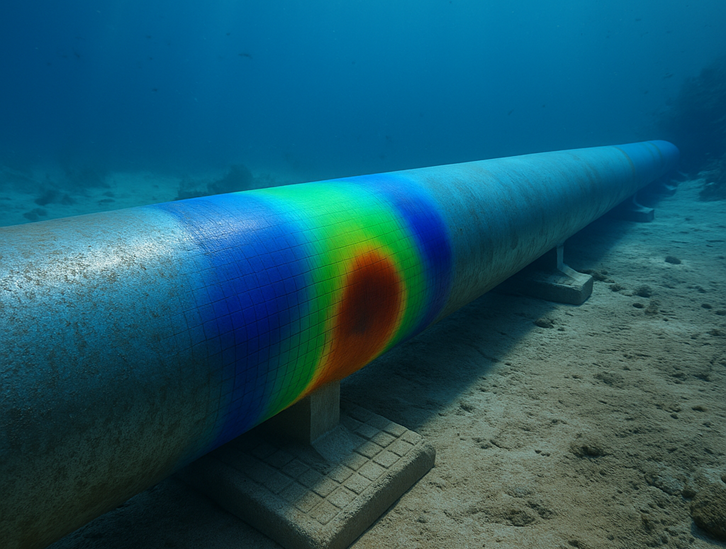
Fig : representative image of subsea pipeline
2. Optimizing High-Pressure Pump Discharge Piping for Performance and Safety
High-pressure pump discharge piping is vital for safely transporting pressurized fluids to downstream equipment. Proper design minimizes pressure loss, prevents vibration and water hammer, and ensures system integrity. Using expansion joints, pulsation dampeners, and proper supports reduces stress and enhances durability. Regular inspections help maintain performance and safety in high-pressure operations.
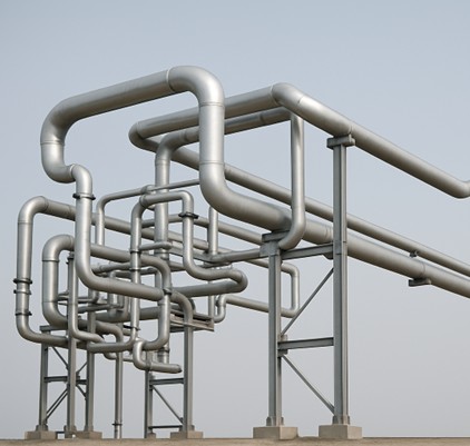
Fig : representative image of Piping system
3. Oil Re-refining Plant
An Oil Re-refining Plant is a highly specialized facility dedicated to processing used lubricants and waste oils, restoring them to a reusable state while advancing sustainability and resource efficiency. Steel structures serve as the backbone of the facility, providing essential support for refining units, distillation columns, and filtration systems. Design & Planning establishes a structurally sound framework, followed by Detailing & Modelling to ensure precision in construction and component integration. Guarantee durability and operational safety, Finite Element Analysis & Structural Analysis are employed to assess performance under elevated temperatures and chemical exposure, ensuring long-term reliability in complex industrial environments.
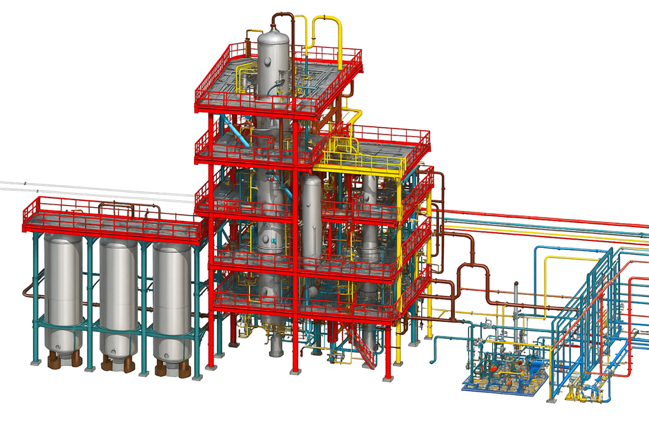
Fig : Oil Re-refining Plant
4. Flaw and Damage Analysis
Finite Element Analysis (FEA) plays a crucial role in evaluating flaws and damage in pressure vessels resulting from corrosion, cracks, or material degradation. During routine inspections, if cracks or wall thinning due to corrosion are detected, FEA enables a detailed assessment to determine the structural integrity of the vessel.
For instance, crack growth analysis is performed using fracture mechanics principles, where FEA calculates critical parameters such as the Stress Intensity Factor (SIF), the J-integral, and the Crack Tip Opening Displacement (CTOD). These metrics help predict how a crack may propagate under operational loading, offering insight into the vessel’s remaining life before potential failure. API 579 provides guidance for using these techniques in Level 3 assessments to decide whether a cracked component can continue operating safely.
In addition to crack analysis, FEA is also instrumental in evaluating corrosion and wall thinning. Pressure vessels commonly face localized corrosion or erosion, which compromises wall thickness and strength. According to API 579, the Remaining Strength Factor (RSF) should be calculated to quantify the vessel’s residual strength. This factor is then incorporated into FEA simulations to model the actual structural behaviour under degraded conditions, ensuring continued safety and performance despite material loss.
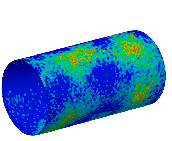
Fig : Flaw and damage analysis
5. Residual Stress and Welding Analysis
Welds introduce residual stresses into pressure vessels, which can significantly affect their performance. FEA simulates these stresses to assess their impact on crack growth, fatigue life, and overall structural integrity. It can also model post-weld heat treatment (PWHT) to reduce residual stresses and optimize the vessel’s performance.
API 579 specifically addresses the effects of welding residual stresses and recommends techniques for evaluating their impact on fitness-for-service. The standard outlines criteria for assessing crack initiation at weld joints and provides methods to determine the adequacy of PWHT to mitigate detrimental effects.
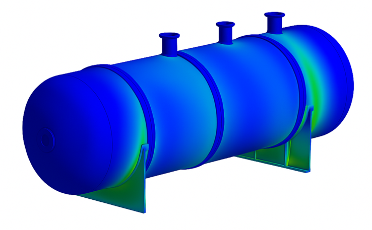
Fig : Post-weld heat treatment (PWHT)
CFD in oil & gas: Simulating the Invisible Forces of Flow and Heat
In the oil and gas sector, the movement of fluids gas, oil, steam, water, or multiphase mixtures drives nearly every process. Computational Fluid Dynamics (CFD) is essential for visualizing and optimizing how these fluids behave inside equipment, pipelines, and atmospheric environments. CFD helps predict pressure drops, flow distribution, thermal performance, erosion, emissions, and ventilation aspects difficult or impossible to measure in real-time.
CFD transforms complex flow physics into clear design insights, reducing risks, increasing efficiency, and ensuring environmental compliance.
Why CFD is Indispensable in Oil & Gas
Fluids in oil and gas facilities often move at high velocities, under extreme pressure and temperature, or with multiphase interactions (solid-liquid-gas). These conditions affect safety, efficiency, emissions, and equipment lifespan.
CFD is especially critical where:
- Flow maldistribution affects process performance.
- Temperature gradients lead to thermal stress.
- Erosion and corrosion compromise reliability.
- Combustion and emissions control are mandatory.
- Ventilation and dispersion affect personnel safety.
Key Applications of CFD
Offshore Applications
Subsea Flow Assurance and Hydrate Prediction
- Codes & Standards: API RP 17N, ISO 13628, DNV-RP-F203
- Simulations evaluate slug flow, hydrate formation, wax deposition, and thermal insulation performance of pipelines and jumpers.
Ventilation of Offshore Modules
- Codes & Standards: NFPA 496, ISO 15138, DNVGL-RP-A201
- CFD ensures gas dispersion and ventilation rates are adequate to prevent flammable gas accumulation in enclosed spaces.
Helideck & Flare Stack Analysis
- Standards Referenced: CAP 437, API 521
- CFD predicts wind turbulence on helidecks and ensures safe dispersal of combustion gases, preventing flame impingement on structures.
Seawater Intake Systems
- CFD ensures optimal pump performance, avoids vortex formation, and maintains uniform flow across intake screens.
Onshore Applications
Combustion & Emissions in Process Furnaces
- Codes & Standards: API 560, EPA CFR 40 Part 60, EN 12952-15
- CFD models burner flame stability, NOx and CO emissions, and heat flux distribution to reduce pollution and improve thermal efficiency.
Refinery Stack and Flare Gas Dispersion
- Codes & Standards: API 521, EPA Dispersion Modelling Guidelines, ISO 23251
- CFD evaluates the dispersion of toxic or flammable gases under varying wind and temperature conditions to maintain safe zones.
Separator & Knock-Out Drum Design Optimization
- CFD simulates phase separation efficiency, internal baffle design, and vortex behaviour for vessels handling gas-liquid or liquid-liquid mixtures.
Erosion Prediction in High-Velocity Piping
- Codes Referenced: API 14E, ASME B31.3 Appendix D
- CFD coupled with erosion models helps estimate material loss in elbows, tees, and throttling devices.
HVAC and Smoke Management in Control Rooms
- Codes & Standards: ASHRAE 62.1, NFPA 92, ISO 17873
- CFD ensures safe air distribution and smoke clearance during fire events, especially in mission-critical buildings.
Types of CFD Analyses Performed
- Steady & Transient Flow Simulations – For both continuous and time-varying flow problems.
- Multiphase Flow Modelling – Gas-liquid, solid-liquid, and slurry behaviour in separators, reactors, or pipelines.
- Thermal Analysis – Heat exchanger performance, thermal mixing, and hot-spot detection.
- Turbulence Modelling – Using RANS, LES, or DES for accurate flow predictions.
- Combustion & Emission Simulation – Predict burner efficiency, flame shape, and pollutant formation.
- Erosion & Deposition Modelling – Coupled with particle tracking for wear rate estimation.
- Gas Dispersion & HVAC Studies – Indoor/outdoor airflow, safety ventilation, and flammable gas control.
CFD Tools Used in the Industry
- ANSYS Fluent / CFX – Widely used for Multiphysics and high-fidelity combustion and flow modelling.
- Siemens Simcenter STAR-CCM+ – For heat transfer, erosion, and rotating machinery.
- OpenFOAM – Open-source tool for custom solvers and large-scale multiphase modelling.
- Autodesk CFD – Used in HVAC and thermal system analysis.
- COMSOL Multiphysics – Coupled flow, heat transfer, and structural response.
- FLOW-3D – Ideal for transient, free-surface flows and erosion modelling.
Here are a few examples of projects successfully delivered by Analyzer in the oil and gas sector, highlighting our deep domain expertise, precision in engineering simulations, and ability to solve complex flow and structural challenges. These projects reflect our commitment to safety, operational efficiency, and innovation in one of the world’s most demanding industries.
1. Enhancing Heat Exchanger Design with CFD Simulation
This CFD simulation of a shell-and-tube heat exchanger showcases detailed temperature distribution and fluid flow patterns. Such analysis helps engineers optimize heat transfer efficiency, reduce pressure losses, and identify potential problem areas like hotspots or flow imbalances. By simulating various operating conditions, designers can enhance thermal performance, ensure structural integrity, and improve the reliability and lifespan of the heat exchanger.
Computational Fluid Dynamics (CFD) plays a crucial role in the design and validation of heat exchangers by providing in-depth insights into complex thermal and flow behaviours. It eliminates the need for multiple physical prototypes, saving both time and development costs. Engineers can simulate real-world conditions such as varying inlet temperatures, flow rates, and pressure levels to predict performance accurately and make data-driven design improvements for robust and efficient heat exchanger systems.
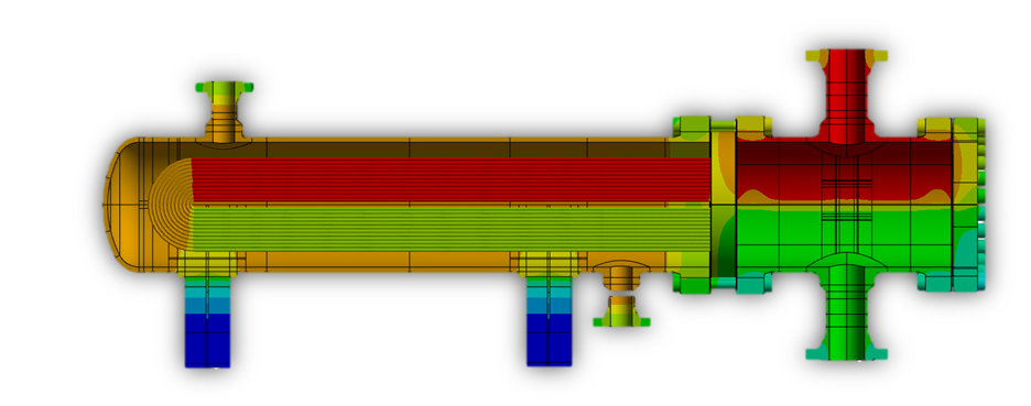
Fig: CFD Simulation of Fluid Flow and Temperature Distribution in a Shell-and-Tube Heat Exchanger
2. CFD Simulation of FGD Absorber System
Computational Fluid Dynamics (CFD) simulation of a Flue Gas Desulfurization (FGD) absorber system provides valuable insights into gas-liquid interactions, droplet dispersion, and pollutant removal efficiency. By visualizing flow fields, velocity vectors, and pressure profiles, CFD helps identify areas of poor mixing, recirculation zones, and maldistribution that can affect SO₂ removal rates. This enables engineers to fine-tune the absorber’s geometry and operating parameters for optimal performance.
Through CFD analysis, the absorber system can be evaluated under various load conditions, helping to predict the impact of inlet gas velocity, spray nozzle configurations, and slurry flow rates on desulfurization efficiency. It also aids in minimizing pressure drop and reducing energy consumption, while ensuring environmental compliance. CFD thus serves as a vital tool in designing efficient, cost-effective, and environmentally sustainable FGD systems.
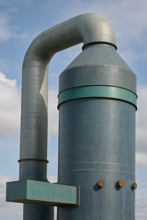
Fig: Representative image of FGD system
3. CFD Analysis of Dispersion Through Exhaust Vent Stack
Computational Fluid Dynamics (CFD) analysis of exhaust vent stacks is critical in understanding the dispersion behaviour of pollutants and gases released into the atmosphere. By simulating various operating conditions—such as wind speed, direction, stack height, and exhaust velocity—engineers can visualize plume trajectories, pollutant concentrations, and ground-level impacts. This allows for early identification of environmental and safety concerns in compliance with air quality standards.
CFD also aids in optimizing the design of vent stacks to achieve efficient dispersion while minimizing recirculation zones and backflow risks. Advanced turbulence models and transient simulations provide insights into real-world unsteady flow effects, enabling better control of emission footprints. As environmental regulations become stricter, CFD proves to be an indispensable tool for designing sustainable exhaust systems in industries such as power plants, refineries, and manufacturing facilities.
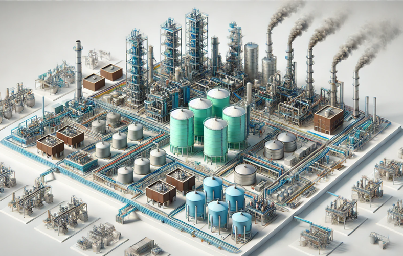
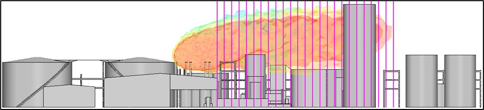
Fig: Representative image of CFD Analysis of Dispersion Through Exhaust Vent Stack
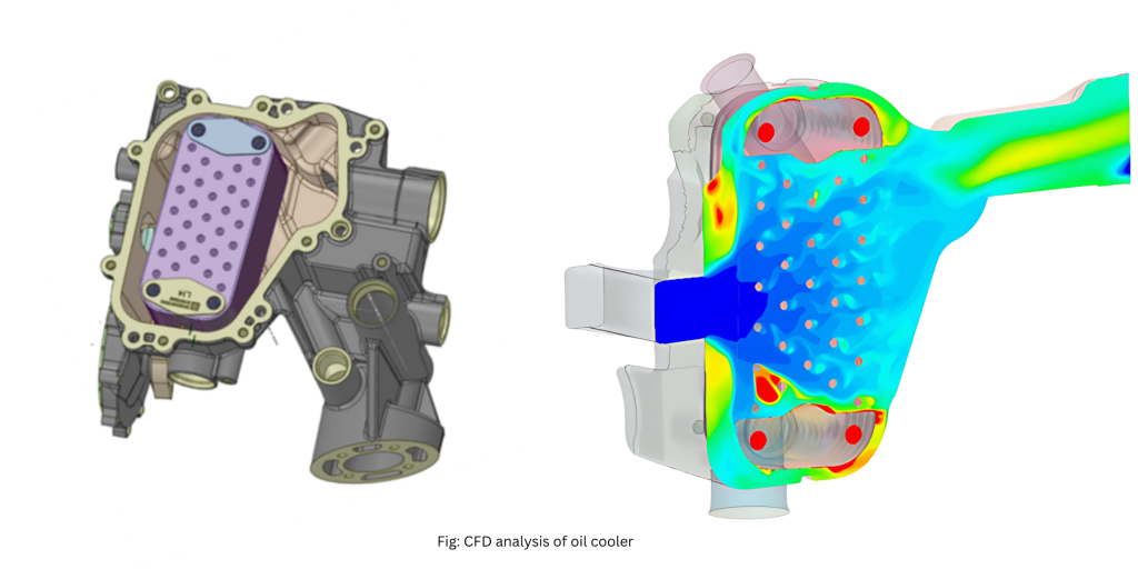
4. CFD Analysis of Oil Coolers in the Oil and Gas Industry
In the oil and gas industry, maintaining optimal operating temperatures of mechanical systems is critical to ensure uninterrupted and efficient operation. Oil coolers play a vital role in regulating the temperature of lubricating and hydraulic fluids used in offshore platforms, refineries, and drilling rigs. Computational Fluid Dynamics (CFD) is increasingly used to simulate and optimize the performance of these oil coolers under harsh environmental and process conditions. By modelling the fluid flow and heat transfer inside the cooler, CFD helps identify inefficiencies such as hotspots, flow separation, and thermal imbalance that could lead to equipment failure or performance degradation.
CFD also supports the customization of oil cooler designs to suit specific applications in upstream and downstream operations. Whether it’s cooling high-viscosity fluids in deep-sea drilling systems or managing temperature in compact heat exchangers for refinery units, CFD allows engineers to test multiple design configurations virtually. This significantly reduces the need for physical trials, cuts down development time, and ensures that the final product is robust, efficient, and capable of withstanding the dynamic conditions typical in oil and gas processes. Through detailed thermal and flow analysis, CFD enhances both the reliability and operational safety of oil cooling systems in the industry.
Why Choose Analyzer CAE Solutions for Your Oil and Gas Needs
In the high-stakes world of oil and gas, precision, safety, and efficiency are non-negotiable. Analyzer CAE Solutions delivers advanced engineering services that cater specifically to the complex challenges of this industry helping you design, analyse, and optimize your operations with confidence.
What We Offer:
- Precision Engineering: From concept to detailed design and simulation, our expertise ensures that your equipment and structures are engineered to perform reliably in the harshest onshore and offshore environments. We work with industry-standard design codes and proven methodologies to deliver dependable results.
- Enhanced Safety and Performance: Our FEA (Finite Element Analysis) and CFD (Computational Fluid Dynamics) services identify potential issues such as structural stress points, flow disruptions, and thermal irregularities early in the design process minimizing risk, improving efficiency, and ensuring regulatory compliance.
- Industry-Specific Expertise: With years of experience in the oil and gas sector, we understand the intricacies of upstream, midstream, and downstream operations. Our solutions are tailored to your project requirements, whether it’s for fixed platforms, floating systems, refineries, or storage facilities.
- Scalable and Flexible Solutions: Whether your project involves massive offshore infrastructure or compact onshore facilities, our engineering services scale to meet the complexity and scope of your operations. We support integrated workflows across disciplines, ensuring consistency and accuracy at every stage.
- Compliance with Global Standards: Our work adheres to leading international standards, including API, ISO, ASME, and DNVGL. We help ensure that your projects not only meet but exceed industry expectations for safety, reliability, and environmental performance.
Choosing Analyzer CAE Solutions means partnering with a team that blends engineering rigor, deep industry knowledge, and commitment to quality. From optimizing designs to ensuring structural integrity and improving system efficiency, we help drive successful outcomes for your oil and gas operations.