
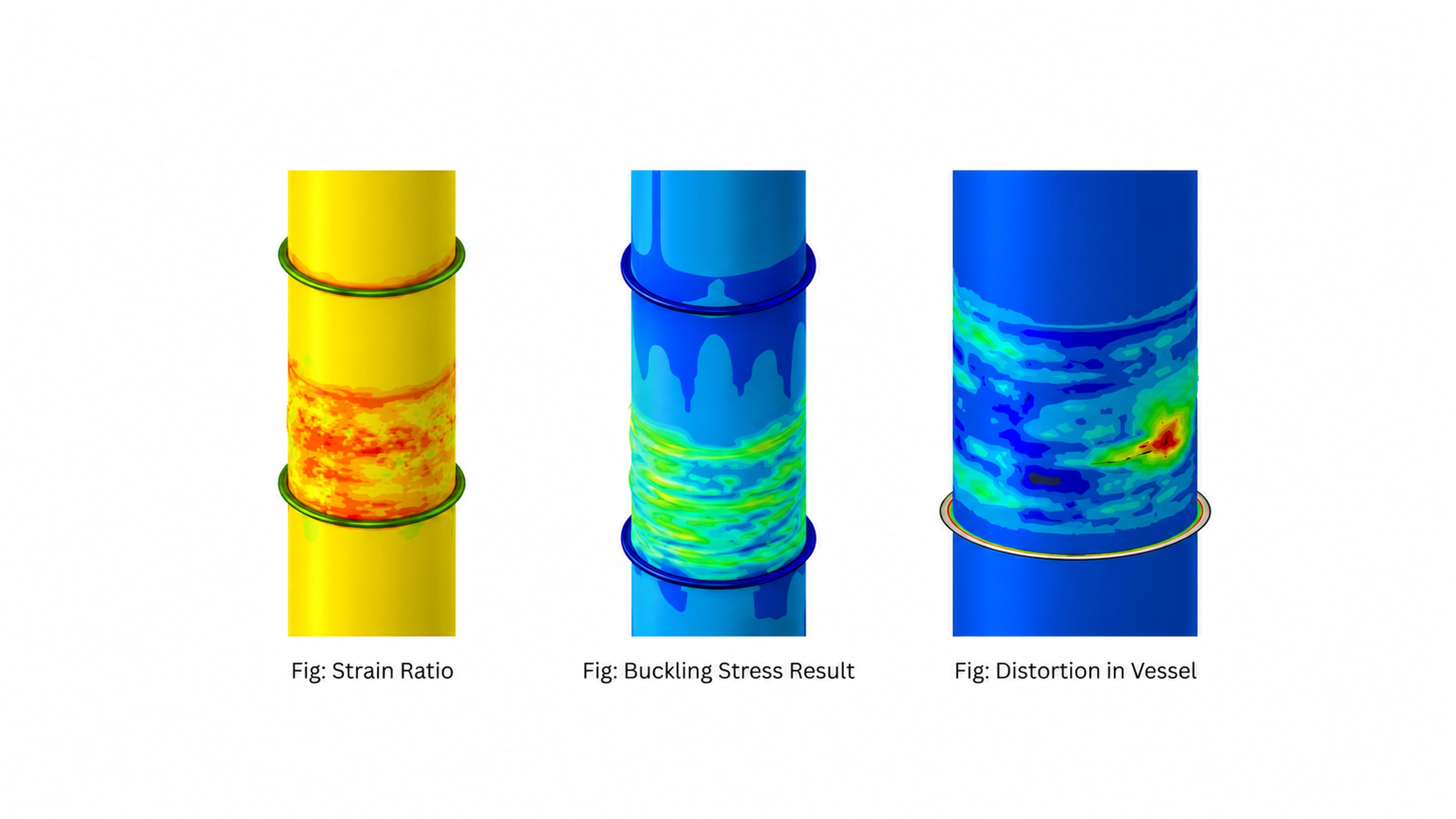
API 579
Fitness-for-Service Assessments
Level 1, 2 and 3 assessments for pressure vessels, piping and storage tanks affected by corrosion, local thinning, pitting, distortion or cracking.
Level 1, 2 & 3
Assessment levels
Parts 5, 6 & 8
Published case studies
10–20 days
Typical turnaround
USA · UK · ME
Clients served
An API 579 fitness-for-service assessment is a structured engineering evaluation of equipment that already contains damage — corrosion, wall thinning, distortion or cracking. It determines whether that equipment can continue operating at its current pressure, whether the pressure must be reduced, or whether repair or replacement is required.
The assessment also establishes a remaining life, which is what sets the next inspection interval. It is carried out to API 579-1 / ASME FFS-1, the standard recognised across refining, petrochemical, power and process industries.
Assessments at all three levels, including Level 3 nonlinear finite element analysis where the simplified methods do not apply.
Most providers stop at Level 2. Level 3 is where the difficult cases are resolved — and where equipment that screening methods reject is often shown to be fit.
When do you need an assessment?
Six mechanisms, six procedures.
Fitness-for-service applies once damage has been found. Each mechanism has its own evaluation procedure and acceptance criteria under API 579.
General metal loss
Overall wall thinning measured across a region of the shell.
Local thin areas
Thinning concentrated in one patch or groove rather than spread evenly.
Pitting corrosion
Many small pits across a surface, individually shallow but collectively significant.
Weld misalignment & distortion
A vessel out of shape, often following PWHT or fabrication tolerance issues.
Crack-like flaws
Cracking found during inspection, assessed using fracture mechanics.
Brittle fracture risk
Equipment operating below its minimum allowable temperature.
What are the three assessment levels?
Less conservative, not more accurate.
The levels differ in conservatism, in the data they require and in who can perform them. The higher levels remove conservatism by doing more work with better data. All three, correctly applied, give a defensible result.
| Criterion | Level 1 | Level 2 | Level 3 |
|---|---|---|---|
| Method | Screening against tabulated acceptance criteria | Detailed calculation using measured thickness profiles | Numerical analysis, normally finite element |
| Data required | Minimum measured thickness | Critical Thickness Profiles, material and operating data | Full geometry, material properties, load and operating history |
| Conservatism | Highest | Moderate | Lowest |
| Performed by | Plant inspector or engineer | Plant engineer or FFS specialist | Specialist analyst with senior review |
| Outcomes | Pass, or escalate to Level 2 | Pass, reduced MAWP, or escalate | Pass, reduced MAWP, or repair |
01
When is a Level 1 assessment enough?
Level 1 is sufficient when the damage is simple and evenly distributed, located away from nozzles, welds and other structural discontinuities, the loading is steady rather than cyclic, and the component passes with margin to spare. If a Level 1 screening passes at the full operating pressure, there is nothing to gain by going further.
02
When do you move to Level 2?
Level 2 applies when the component fails Level 1, or when the Level 1 assumptions do not match the damage — thinning concentrated in one region, damage near a discontinuity, or a result that only marginally fails. Level 2 uses the measured thickness profile rather than a single worst reading, so it recovers margin that Level 1 discards.
03
What forces a Level 3 assessment?
Level 3 is required when the geometry, loading or damage falls outside what the Level 1 and Level 2 rules cover. Typical triggers are distortion that cannot be idealised using the simplified geometric representations Level 2 requires, damage spanning a structural discontinuity, cyclic or thermal-transient service, interacting damage mechanisms, and operation in the creep range.
Which API 579 Part applies to your damage?
Damage type decides the procedure.
Each damage mechanism is assessed under a specific Part of API 579-1 / ASME FFS-1. The Part determines the procedure, the data required and the acceptance criteria.
| Part | Damage type | What it covers |
|---|---|---|
| Part 3 | Brittle fracture | Risk of sudden failure at low temperature or in low-toughness material |
| Part 4 | General metal loss | Wall thinning distributed across a region |
| Part 5 | Local metal loss | Thinning concentrated in a patch or groove — Local Thin Areas |
| Part 6 | Pitting corrosion | Arrays of pits, assessed on density, depth and spacing |
| Part 8 | Weld misalignment and shell distortion | Out-of-roundness, peaking, bulging and misaligned weld joints |
| Part 9 | Crack-like flaws | Cracking assessed using fracture mechanics and a failure assessment diagram |
The case studies below show assessments carried out under Part 5 (local metal loss), Part 6 (pitting corrosion) and Part 8 (weld misalignment and shell distortion).
When is a Level 3 assessment required?
Where the simple rules run out.
Level 3 applies where the measured damage cannot be represented by the idealised geometry the simpler methods assume. It is the part of fitness-for-service work most often outsourced.
What it does differently
It builds a finite element model of the actual damaged geometry rather than approximating it, calculating the real stress and strain distribution. That allows it to demonstrate adequate strength in cases the simplified methods have to reject on conservatism alone.
When simplified methods stop applying
Level 1 and Level 2 rely on idealised geometry — a single thinned rectangle, a uniform out-of-roundness, a defined pit array. When the measured damage cannot be represented that way, the rules themselves direct the assessment to Level 3. That is a limitation of the method, not a sign the equipment is unfit.
What our models include
Actual distorted or thinned geometry mapped from inspection data. Wall thickness reduced by the agreed future corrosion allowance. Elastic-plastic material behaviour with strain hardening. Nonlinear geometric effects. Where stability governs, buckling analysis under the combined pressure and external loading.
What it demonstrates
Protection against plastic collapse, local failure through strain limit checks, and structural stability under the governing load combinations — each evaluated against the acceptance criteria in API 579-1 / ASME FFS-1.
What data do you need to start an assessment?
And how the assessment runs.
Five stages from receiving your data to issuing a recommendation. Most assessments conclude before reaching the last of them.
What we need from you
- Inspection data — point thickness readings, or Critical Thickness Profiles for a Level 2 or Level 3 assessment
- Vessel drawings and the design data sheet
- Material specification
- Design and operating pressure and temperature
- Operating history, including any upset conditions
- The damage mechanism, if already identified
- The future corrosion allowance to be applied
Data collected for a Level 1 screening is often insufficient for a Level 2 or Level 3 assessment. Scattered point readings cannot build a Critical Thickness Profile. Deciding the likely level before the inspection team demobilises avoids a second site visit.
How we carry out an assessment
01
Data review and scoping
We review the inspection data and design information, confirm the damage mechanism, and identify the applicable assessment level and API 579 Part.
02
Screening assessment
A Level 1 evaluation against the tabulated acceptance criteria. If it passes at the required pressure, the assessment concludes here.
03
Detailed or numerical assessment
Where Level 1 does not pass or does not apply, we proceed to a Level 2 calculation or, where the rules require it, a Level 3 finite element analysis.
04
Code compliance evaluation
Results are checked against the acceptance criteria in API 579-1 / ASME FFS-1 and the applicable design code.
05
Report and recommendation
A report setting out the assessment, the results, the remaining life and a clear recommendation on continued operation.
What does a fitness-for-service report contain?
And how long it takes.
Every assessment ends with a clear answer on continued operation, plus the remaining life figure that sets your next inspection interval.
How long does an API 579 assessment take?
| Simple assessments | 5–15 days |
| API 579 & multi-load-case | 10–20 days |
Durations run from receipt of complete inspection and design data. The timeline extends where data arrives incomplete or in stages, where scope changes during the assessment, or where supplied data needs validation first. We review the inputs and confirm a timeline before starting, rather than quoting a date and revising it later.
- Scope of the assessment and the damage characterisation
- Inspection data used and the assumptions applied
- Assessment level, API 579 Part and methodology
- Load cases and boundary conditions
- Calculated results — Remaining Strength Factor, stress and strain results, or recalculated MAWP
- Code compliance summary against the acceptance criteria
- Remaining life estimate based on the agreed future corrosion rate
- Conclusion and recommendation
Fit for continued service
The equipment is acceptable at its current MAWP and operating temperature.
Fit at a reduced MAWP
A recalculated maximum allowable working pressure at which continued operation is acceptable.
Not fit for service
Repair, replacement or further mitigation is required.
Fitness-for-service assessments we have carried out.
Level 1 pass, Level 2 de-rate, Level 3 analysis.
Between them these three show the full escalation path, with the real outcome in each case.
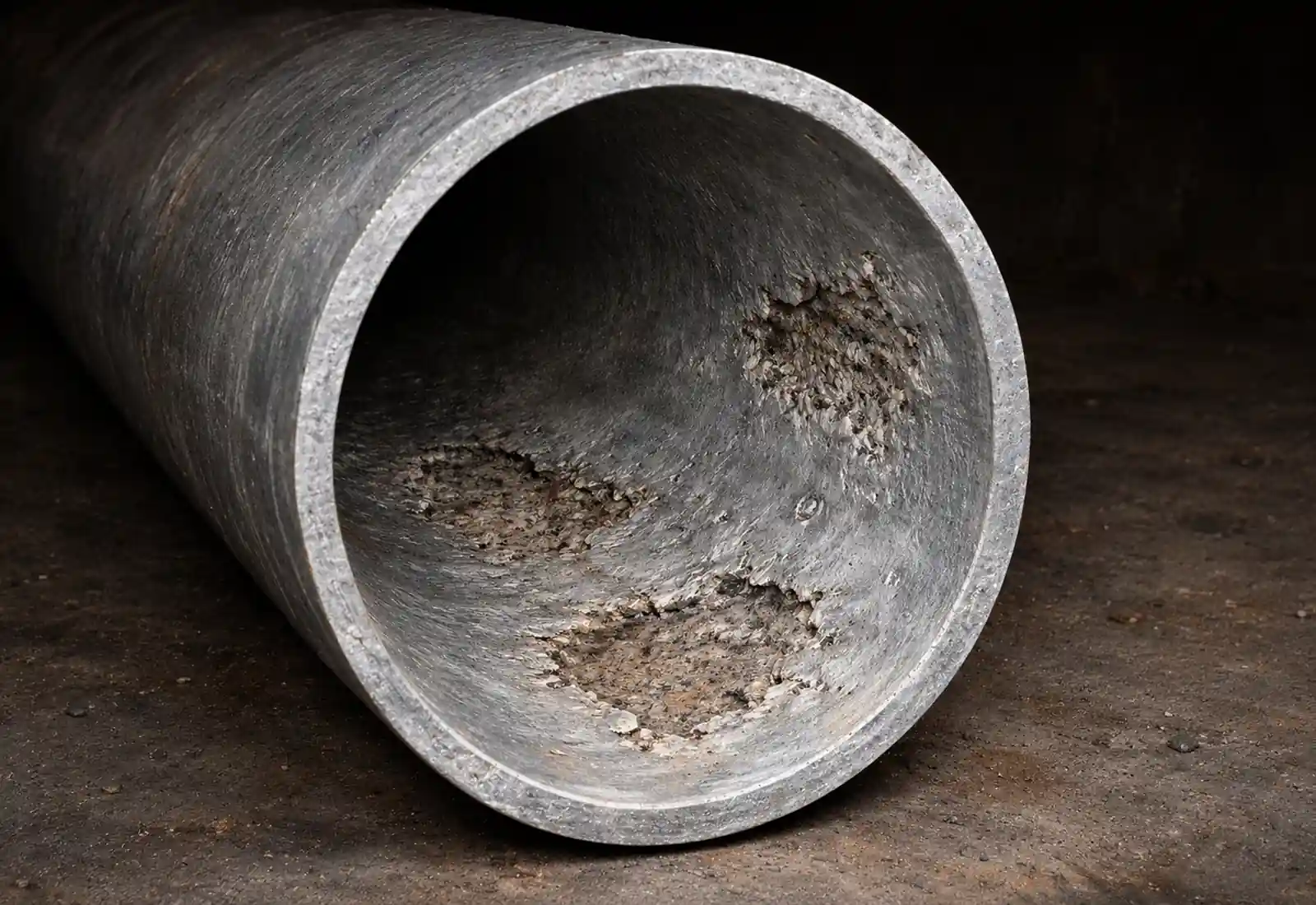
Pitting corrosion in a pressure vessel shell
The problem
Pitting corrosion was identified across the surface of a carbon steel pressure vessel shell during inspection. The assessment had to establish whether the pitted region remained acceptable at the operating pressure, or whether the vessel needed to be de-rated.
The outcome
A Level 1 assessment under Part 6 was carried out against the tabulated acceptance criteria. The minimum remaining thickness exceeded the allowable limit and the recalculated MAWP exceeded the operating pressure. The vessel was confirmed fit for continued service, with no escalation to Level 2 required.
Level 2
Part 5
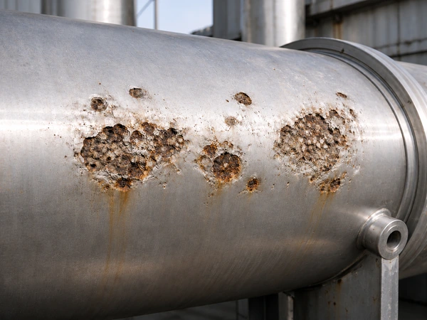
Local Thin Areas in a cylindrical shell
The Remaining Strength Factor fell below the acceptance criterion at design pressure, so a reduced MAWP was calculated at which continued operation was acceptable.
Level 3
Part 8 + Annex 2D
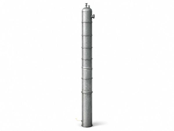
Shell distortion after post-weld heat treatment
Distortion that could not be idealised for Level 2 was assessed by three-dimensional nonlinear finite element analysis, demonstrating protection against plastic collapse and adequate stability. Continued operation was confirmed.
Who carries out and reviews the assessment?
Director-level sign-off on every report.
Assessments are produced by our analysis team and reviewed before issue. Client data is handled under NDA throughout.

Dharani Madala
Director · Analyzer CAE Solutions
- M.Tech in Aerospace Engineering, IIT Bombay — Departmental Topper
- B.E. in Aeronautical Engineering — University Gold Medalist
- All India Rank 1, GATE 2002
- Has guided over 400 advanced CFD and FEA projects
- Works to ASME Section VIII, ASME Section III, PD 5500, API 650 and API 610
Every assessment is reviewed at director level before the report is issued.
Client drawings, inspection data and reports are handled under NDA with controlled internal access. We work across US, UK and Middle East time zones, so assessment work continues outside Indian working hours.
Frequently asked questions.
Before an assessment begins.
The questions we are asked most often by integrity and inspection teams.
01
How much does an API 579 assessment cost?
Assessments are quoted as a fixed price once the scope is confirmed. Cost is driven by the number of damage locations assessed, the assessment level required, the number of load cases, whether fracture mechanics or creep evaluation is involved, and the condition of the inspection data supplied. Send us the data and we will confirm scope and price.
02
Does fitness-for-service apply to piping and storage tanks, or only pressure vessels?
API 579-1 / ASME FFS-1 applies to pressure vessels, piping and storage tanks. The assessment procedures are the same; what changes is the design code the equipment was built to and the acceptance basis applied.
03
What corrosion rate do you assume when calculating remaining life?
Where the client has inspection history, we use their measured rate. Where none is available, we agree a rate before starting, based on the damage mechanism and service conditions. The assumed rate is always stated clearly in the report, because the remaining life figure depends entirely on it.
04
Can you support an assessment during a plant shutdown?
Yes. We work with clients across the United States, the United Kingdom, the Middle East and Europe, so assessment work continues outside Indian working hours. Shutdown assessments are time-critical and depend heavily on inspection data arriving complete, so tell us your constraint when you send the data and we will confirm what is achievable.
05
What is the difference between API 579-1 and ASME FFS-1?
They are the same document. API 579-1 / ASME FFS-1 is published jointly by the American Petroleum Institute and ASME, so the two designations refer to a single standard.
06
Does the choice of analysis software affect acceptance of the result?
No. What matters is that the method follows API 579, that the assumptions and load cases are stated explicitly, and that the report shows the code checks against the acceptance criteria. The software is a tool for producing those results.
07
What if our inspection data is incomplete or inconsistent?
We review the supplied data before starting. Where readings are inconsistent, where the coverage is insufficient for the assessment level required, or where the damage characterisation does not match the measurements, we identify that first and tell you what is needed. Analysing to a flawed data basis produces a result nobody can rely on.
Send us your inspection data.
We will tell you which level applies.
Our senior engineers will confirm the applicable assessment level, the data we still need, and respond with scope and an indicative quotation.