Introduction
Solenoid valves are critical components in modern Thermal Management Systems (TMS), responsible for precise control of airflow and pressure regulation. Their efficient operation directly affects system responsiveness, stability, and overall performance across a wide range of thermal applications.
In this study, Analyzer CAE conducted a detailed Computational Fluid Dynamics (CFD) analysis to investigate the internal flow characteristics and performance behaviour of a solenoid valve used within a TMS assembly. The aim was to gain an in-depth understanding of the flow path, pressure distribution, and loading effects on the plunger wall under actual working conditions.
By combining advanced CFD simulation techniques with domain expertise, the analysis provided valuable insights into the aerodynamic forces acting on the plunger and how downstream resistance impacts flow behaviour. This data-driven approach enabled design optimization for better reliability and flow uniformity before physical prototyping.
Objective
The objective of the simulation was to:
- Evaluate flow distribution and velocity characteristics through the valve section.
- Assess forces acting on the plunger surface due to air flow.
- Understand the impact of back pressure and downstream resistance on valve performance.
Approach
The analysis was performed using an axisymmetric CFD model of the solenoid valve, representing a section of the full geometry for computational efficiency.
Key highlights of the methodology include:
- Air modelled as a compressible ideal gas.
- SST k–ω turbulence model used to capture near-wall flow behaviour.
- Transient flow simulation performed to achieve steady-state convergence.
- Boundary conditions replicated actual working conditions of the valve within the TMS assembly.
Two primary scenarios were considered:
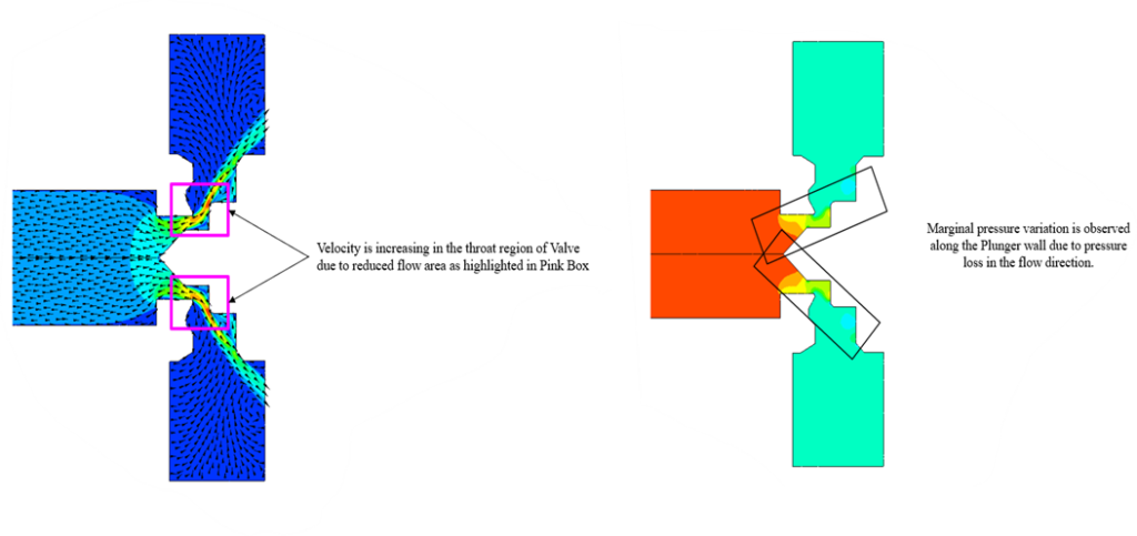
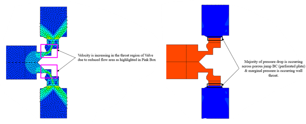
- Baseline case – Valve operating under nominal back pressure.
- Modified case – Valve with an equivalent porous restriction downstream, representing a perforated plate effect.
Observations
- The velocity contours showed an increase in flow speed through the throat region, indicating efficient flow acceleration.
- Pressure distribution revealed a steady pressure drop along the flow direction, confirming uniform flow and minimal recirculation.
- Under the modified downstream condition, flow became slightly radial due to added back pressure, highlighting how downstream resistance can influence internal flow trajectory and loading on the plunger wall.
- The forces computed on the plunger wall remained within design safety limits, validating structural adequacy for both conditions.
Outcome
The study successfully:
- Provided a validated understanding of internal flow physics within the solenoid valve.
- Helped optimize valve design for better flow stability and reduced pressure losses.
- Demonstrated Analyzer CAE’s capability to simulate realistic operating conditions and evaluate performance-critical parameters for electro-mechanical fluid components.
Conclusion
This CFD study showcased Analyzer CAE’s ability to combine advanced simulation techniques and engineering expertise to deliver actionable insights on compact, high speed valve systems.
Our detailed understanding of flow structure interaction and parametric evaluation enable clients to refine their designs before prototype testing saving time, cost, and development cycles.