Client: Leading EV Charging Manufacturer
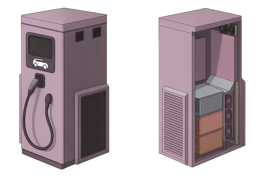
To support the growing demand for high-speed electric vehicle (EV) charging infrastructure, a leading EV charging manufacturer embarked on the development of a next-generation compact fast charger. This advanced charging unit was engineered to deliver high power output within a space-efficient footprint, making it ideal for urban deployments, commercial fleets, and highway corridors. As part of the Thermal Optimization of High-Power EV Charger initiative, it was also designed to operate reliably under harsh environmental conditions, including high ambient temperatures, dust exposure, and continuous usage cycles.
The system integrated multiple high-capacity EV modules within a sealed enclosure, optimizing space without compromising on performance. However, as the internal power density of the charger increased, the manufacturer identified potential risks associated with thermal buildup. Excessive heat could degrade electronic components, reduce operational efficiency, and lead to premature failure, especially in regions where ambient temperatures regularly exceed 40°C. This triggered the need for a detailed CFD thermal analysis of EV charger and ventilation strategy to ensure that the internal components remain within safe temperature thresholds under all operating scenarios. The objective was to validate the existing design and explore opportunities for enhancing airflow, minimizing hot spots, and ensuring long-term reliability across a range of deployment conditions.
Challenge
Each EV module in the charger was rated 150 kW, producing approximately 7.5 kW of heat per module during continuous operation. Early testing revealed hotspots approaching 72°C, particularly near the module walls, raising concerns about:
- – Inadequate cooling airflow
- – Elevated thermal stress on components
- – Short-circuiting of airflow paths
- – Overheating in high ambient temperatures (up to 45°C)
- – Risk of thermal shutdowns or power derating under sustained loads
- – Uneven airflow distribution causing localized hotspots
To address these issues and meet the objectives of the Thermal Optimization of High-Power EV Charger, the client requested a detailed CFD thermal analysis of EV charger to:
- – Study airflow behavior and temperature distribution
- – Optimize fan configuration and placement
- – Improve ventilation paths and filter layout
- – Support design decisions for thermal reliability
- Ensure safe operation without triggering thermal protection systems
- Validate performance across different environmental and usage scenarios
Solution: CFD-Based Thermal Simulation
As part of the Thermal Optimization of High-Power EV Charger, a steady-state CFD thermal analysis of EV charger was performed to replicate operating conditions and assess thermal performance.
Simulation Setup:
- – Geometry modeled from CAD source of the charger enclosure
- – Each EV module simulated with uniform heat generation
- – Axial fans modeled using fan curve boundary conditions
- – Inlet and exhaust filters incorporated with pressure resistance
- – Dry air used as the working fluid, with realizable k-ε turbulence model
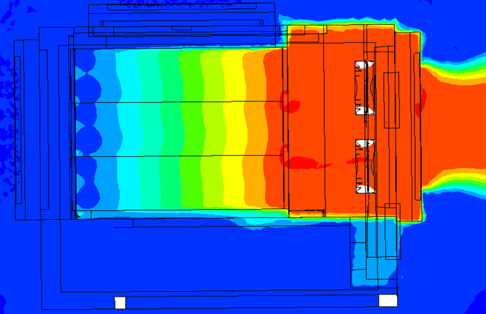
- – Focused on airflow velocity, recirculation, and heat removal efficiency
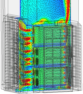
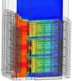
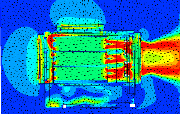
Fig : Contour Coloured by Velocity Magnitude & Temperature
Key Results
Fan Operating Points:
| Component | Flow Rate (m³/hr) | Static Pressure (Pa) |
| Internal module fans | 320 | 550 |
| Top exhaust fan | 950 | 600 |
| Bottom exhaust fan | 520 | 780 |
| Total System Flow | ~4300 | 1450 |
Thermal Findings:
– Maximum observed temperature on module surfaces: ~85°C
– Temperature rise across modules: 35–40°C (vs. target <15°C)
– No recirculation or short-circuiting of air detected
– Low-velocity zones identified behind module support structures
Outcome & Recommendations
The CFD analysis enabled the team to pinpoint inefficiencies in thermal performance and recommend specific design changes:
– Upgrade fan capacity or use dual-fan redundancy
– Introduce air deflectors to reach stagnant pockets
– Reduce resistance by optimizing filter mesh specifications
– Consider passive cooling enhancements for heat-prone surfaces
These measures were projected to bring down peak internal temperatures by 8–10°C, improving overall thermal safety margins.
Conclusion
By leveraging CFD simulation early in the design phase, the leading EV charging manufacturer was able to validate thermal behavior, avoid costly physical prototyping, and confidently proceed with design enhancements.
The resulting charger is now better equipped to operate safely and efficiently in high-temperature environments, supporting sustainable EV adoption in urban and industrial applications.